How-To Repair a Desktop LCD with Bad Capacitors.
LCD Monitors can fail for a variety of reasons, one of the primary reasons they fail is due to faulty capacitors. Symptoms of capacitor failure are,
|
|
Picture flickering
|
|
|
Slow startup
|
|
|
LED power light on, no picture.
|
It only takes a couple of hours to disassemble the monitor, remove the old capacitors, and install new ones. Tools needed are a Radio Shack soldering iron, Phillips head screwdriver, putty knife, X-Acto knife or single edge razor blade and a pair of wire cutters.
LCDalternatives sells capacitor rebuild kits for many different types of LCD monitors. The kits range in cost between $12 and $15. If we don’t have your model, email us at info@lcdalternatives.com and we will assemble a kit for you. We will discount the new kit 50%, our way of saying thanks for the new kit.
If you would like to view a more in depth repair video, we have one at YouTube Video. The video shows a Viewsonic VG2021m being repaired. An in depth repair tutorial is located at www.lcdalternatives.com. This repair tutorial shows a Samsung 204T being repaired.
Good Luck with your repair! Remember, never work on an LCD monitor while it is plugged in!
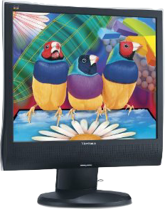
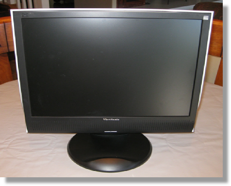
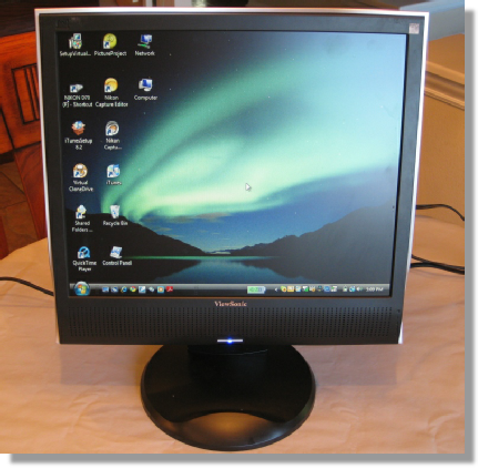
This is a Viewsonic VA930M LCD Monitor. The power LED comes on, but the screen remains black. This is a classic sign of a monitor with bad capacitors.

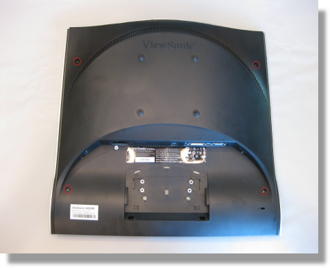
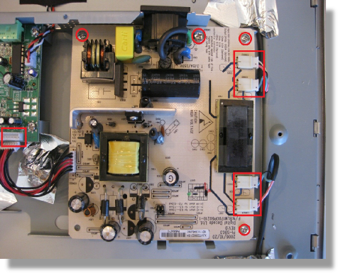
First, remove the base. There are four screws attaching it to the back. There are another four screws holding the front and back halves of the monitor together. Remove the four screws circled in red. Separate the front from the back using the putty knife.
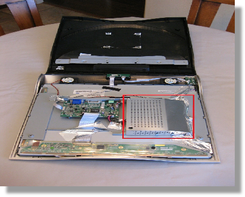
Here you can see the video board on the left side, and the power supply board. There’s an aluminum cover on the power supply board. Remove the screws and tape. Lift the cover away.
Before you remove the four plugs, use a permanent marker and mark them so that you will remember what plug goes where. Remove the plug on the video board. Remove the four screws. Take note, the screw on the top is larger than the others.
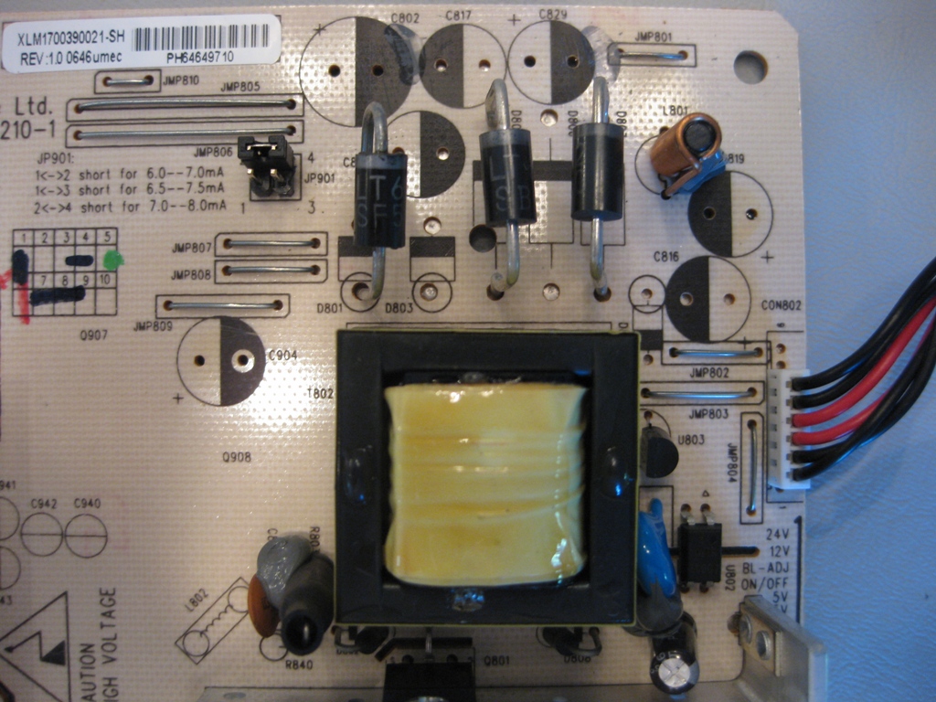
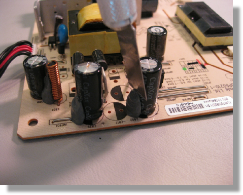
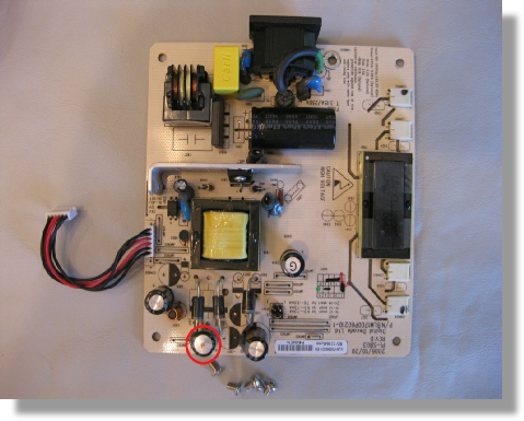
This is the power supply board. The capacitor on the bottom is visibly bulged. This is an indication that it needs to be replaced. You should replace all of the capacitors while the board is out of the monitor.
Before removing the capacitors examine them, and remove any gray or white glue holding them in place on the board. Use an X-Acto knife.
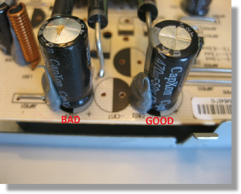
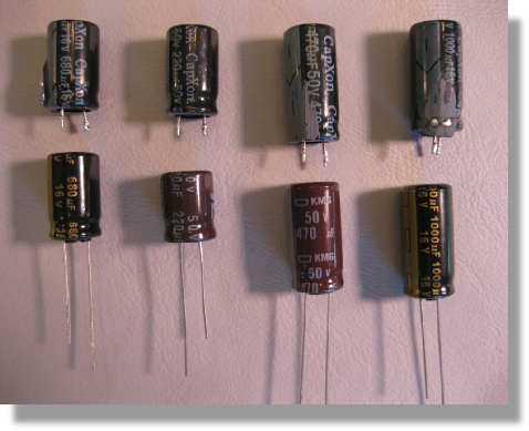
The capacitor on the left, marked bad, is obviously bulged. The capacitor on the right looks normal. Capacitors can look normal and still need to be replaced. You can replace a lower voltage capacitor with a higher voltage capacitor, but not vise versa.
The capacitors have been removed. Note the shaded area on the board. This is the negative side and the un-shaded part is the positive side. Always match the negative side of the capacitor to the negative side of the board.
This video shows how to remove a capacitor. While gently pushing on one side, heat up the corresponding led. The led will pull out of the hole. Repeat. If the capacitor is being stubborn, reheat the solder and gently pull the capacitor away from the board.
The capacitors on the top were removed. The ones on the bottom are the replacements. If you examine the capacitors, you will see that there is a stripe on one side, this is the negative side of the capacitor.
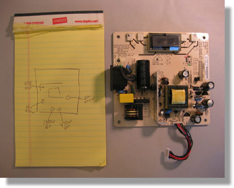
Before you remove the capacitors, make a sketch of their location. If you skip this step, you will regret it later on!
Soldering is easy. Make sure your solder iron is clean and HOT. Test it by touching a little solder to the tip. When it melts, it’s ready to use. Using the solder provided in the kit, apply heat to the joint, for a second or two, then apply the solder. It should flow quickly.
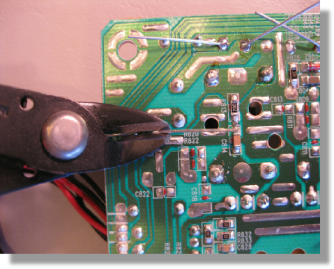
After you have soldered all the joints, use a pair of wire cutters to trim off the excess. Re-assemble the monitor.
You did it!